 Robotics
Publications
 Robotics
Publications
Robotics
PublicationsR.T. Laird, H.R. Everett, G.A. Gilbreath, T.A. Heath-Pastore, R.S. Inderieden
Naval Command Control and Ocean Surveillance Center
RDT&E Division 531, San Diego, CA 92152-7383
Point of Contact: 619-553-3667 or laird@nosc.mil
K. Grant
Computer Sciences Corporation
4045 Hancock Street, San Diego, CA 92110-5164
The Naval Command Control and Ocean Surveillance Center (NCCOSC) RDT&E Division (NRaD) has developed a command and control architecture to provide coordinated control of multiple autonomous interior and exterior vehicles from a single host console. The Multiple Robot Host Architecture (MRHA) is a distributed multiprocessing system that can be expanded to accommodate as many as 32 remote platforms. The initial application will employ eight Cybermotion K2A Navmaster robots configured as remote security platforms in support of the Mobile Detection Assessment Response System (MDARS) Program. This paper discusses the evolution of the command, control, and communications aspects of the MRHA, including the current status of Interior developmental testing in an operational warehouse environment at Camp Elliott in San Diego, CA.
The MDARS Interior platform has successfully demonstrated sustained autonomous navigation within a semi-structured warehouse environment (i.e., with periodic and unpredictable relocation of odd-shaped objects, and few definitive walls for navigational referencing). The ability to detect intruders using passive infrared and microwave motion detection sensors has been implemented and extensively tested (Smurlo & Everett, 1993). A Broad Agency Announcement (BAA) contract was awarded in 1995 to Cybermotion, Inc., Salem, VA, to improve the probability of detection and integrate an additional capability to perform automated inventory assessment using interactive RF transponder tags.
 Figure 1.
The early MDARS Interior feasibility prototype on patrol in Building
F-36 at the Naval Command Control and Ocean Surveillance Center, San Diego, CA.
The MDARS Exterior program extends the robotic security and inventory control concepts of MDARS Interior into the realm of semi-structured (i.e., improved roads, defined fence lines, and standardized storage layouts) outdoor environments such as storage yards, dock facilities, and airfields. Intruder detection, assessment, and response, product inventories for theft prevention purposes, and lock/barrier checks are some of the physical security and inventory tasks currently performed by government personnel that will be replicated by the exterior robots (Everett, 1995). Inventory control will consist of verifying the contents of closed structures (i.e., warehouses, bunkers, igloos) without the need for opening. As is the case for the Interior program, the user's desire for minimum human involvement dictates that the exterior system operate in a supervised autonomous mode.
The MDARS Exterior development effort began in 1994 with the award of a three-year Broad Agency Announcement contract to Robotic Systems Technology (Myers, 1994; 1995) for the development of two brassboard platforms equipped with autonomous-navigation, collision-avoidance, and intruder-detection capabilities. A preliminary prototype was successfully demonstrated in October 1994 and several component-level sensor systems have been evaluated off-platform. NCCOSC is expanding the MRHA as initially developed for the Interior system to provide supervisory command and control functions for the exterior robots (Heath-Pastore & Everett, 1994). The final system will be capable of supporting a mix of interior and exterior platforms to offer site commanders great capability and flexibility in an automated security solution. The Phase-I BAA effort will culminate with a technical feasibility demonstration at a Government site towards the end of 1997. The follow-up Exterior phase will provide enhancements such as intruder detection on the move and a non-lethal response capability.
From a technical perspective, the MDARS objective is to field a supervised robotic security system which basically runs itself until an unusual condition is encountered that necessitates human intervention. This requirement implies the host architecture must be able to respond to exceptional events from several robots simultaneously. Distributed processing allows the problem to be split among multiple resources and facilitates later expansion through connection of additional processors. The individual processors are connected via an Ethernet LAN (Figure 2) that supports a peer-to-peer communications protocol. This distribution of function enables human supervision and interaction at several levels, while the hierarchical design facilitates delegation and assignment of limited human resources to prioritized needs as they arise (Everett, et al., 1994).
The Supervisor computer sits at the top of the hierarchy, responsible for overall system coordination and graphical display of the "big picture." The Supervisor has at its disposal a number of computing resources, such as one or more Operator Stations , two or more Planner/Dispatchers , a Product Assessment Computer , and a Link Server . The Supervisor and Operator Stations have been similarly configured to provide the guard with consistent user-friendly visual displays. Both modules support a point-and-choose menu interface for guard-selectable options, commands, and navigational waypoints. The Operator Station allows a security guard to directly influence the actions of an individual platform with hands-on control of destination, mode of operation, and camera functions. An optional Virtual Reality Display can be connected to the network if desired to provide a realistic three-dimensional model of the operating environment (Everett, et al., 1993).
The Planner/Dispatcher computers (an integration of the Cybermotion Dispatcher and the NCCOSC Planner ) are responsible for navigation and collision avoidance. The Link Server provides an interface to a spread-spectrum RF link between the host and the various robots, and maintains a blackboard data structure of robot status information for immediate retrieval by other computers on the LAN.
The Product Database Computer maintains a listing of high-value inventory as verified by an RF tag reading system onboard the robot, correlated to geographical location within the warehouse. The Product Assessment Computer is responsible for downloading RF tag data from each robot, and for transferring the raw data to the Product Database Computer . Database Access Computers perform the inventory position estimation function using the raw tag data collected over time. They also provide an automated interface between the MDARS Product Assessment System and existing site database systems such as Distribution Standard System (DSS) or Standard Depot System (SDS) .
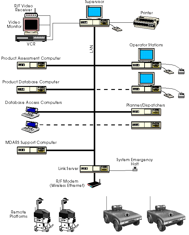
Figure 2. Block diagram of the Multiple Robot Host Architecture developed for the coordinated control of multiple platforms.
The optional MDARS Support Computer performs the automated attendant processing, monitoring all robot activity and reporting emergency conditions via telephone to technical support personnel. Once telephone contact has been made, DTMF (touch-tone) commands will be used to query robot status and to switch between fixed-installation surveillance cameras.
Inter-processor communication is currently carried out over an Ethernet network using the IPX/SPX networking protocol on a peer-to-peer connection-oriented basis. Host-vehicle communication is carried out over a wireless RF modem network using the ARLAN 010/110 and ARLAN 150 RS-232 serial modems. The ARLAN 150s act as both end-point transceivers and as stand-alone repeater/routers. The interface used for inter-processor communication consists of a software stack based upon the OSI/ISO reference model as shown in Figure 3. Data is passed from the application program at the top of the stack through the various layers until it is transmitted over the LAN to the receiving application program.
       Application             Ada/C Application Program

      Presentation                  MRHA Network API

         Session                    MRHA Network API

        Transport                         SPX

         Network                          IPX

        Data-Link                  NIC Packet Driver

        Physical                    Ethernet Thinnet

 ISO/OSI Reference Model           MRHA Inter-Processor Model
The present serial interface between the Link Server and the Interior remote platform is depicted in Figure 4. Commands issued by the Link Server to the remote platform pass through the multi-port serial board to the ARLAN R/F modem on the host and are received by the modem on the remote platform. The Scheduler processes the commands and returns the response to the host.
The current data-throughput requirements for both inter-processor and host-vehicle communications are relatively low. Teleoperation of a remote platform from the Operator Station places the highest demand upon the network and involves a "real-time" control loop that requires a minimum update rate of approximately 3-5 Hz. This equates to a minimum Ethernet packet rate of approximately 10 packets/second and a through-the-air baud rate of approximately 4800 baud.
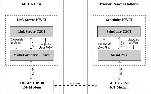
Figure 4. Serial interface between the Link Server and interior remote platform.
Full and effective coverage of the remote operating area by the RF modem network is a significant logistical and technological problem. The selected ARLAN modems operate in the 900-MHz frequency range and are limited in output power to approximately 1 watt. Reliable coverage typically requires multiple transmitters and/or multiple repeaters placed strategically about the area of operation. Tests have been performed to quantify the power dispersion pattern of the modems in an attempt to validate observed "null" zones where improved coverage is needed. Figure 5 maps received power as a function of position within Bay 3 of the Camp Elliott warehouse where the MDARS Interior robot is currently installed. The modem is situated adjacent to the peak power level reading near X-Y position (-50, 0).
The ARLAN 100 -series modems are sufficient for low data rate operation where a large area must be covered. The use of repeaters is usually required and necessarily degrades data throughput (e.g., each hop through a repeater can reduce the effective data rate by 50%). In order to support such planned capabilities as compressed video/audio transmission, however, higher throughput devices are required as will be addressed in Section 6.
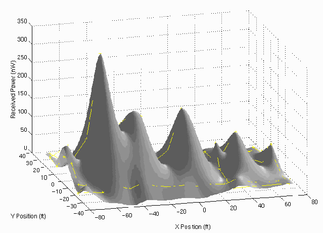
Figure 5. RF power dispersion pattern of ARLAN 150 modem within the Camp Elliott warehouse environment.
A number of "non-deliverable" enhancements have been made to the MRHA to facilitate remote system monitoring and maintenance during final developmental testing prior to installation at the first user site. A computer-controlled video switch has been installed and connected to eight fixed surveillance cameras that cover the entire patrol area of Bay 3 within the Camp Elliott warehouse. The video switch is controlled by software running on the MDARS Support Computer that tracks a designated robot's progress during patrols; as the robot moves into the field of view of a particular camera, the appropriate video signal is automatically selected and routed back to the control van. Video from a steerable camera onboard the robot is also routed on a separate channel back to the control van. Both video channels are input to a Gyyr FasTrans 2000 remote video surveillance system that is capable of transmitting a single selectable channel to a remote monitoring station over ordinary telephone lines. This remote monitoring feature allows operators or technicians to view live video of an installation site from their home office while performing diagnostic or maintenance activities.
 Figure 6. The MDARS Interior robot equipped with the Cybermotion
SPI Module on patrol in the Camp Elliott warehouse in San Diego, CA.
To complement the remote video capability, an "automated attendant" function has been added to the MDARS Support Computer to provide an emergency dial-out capability: if an unrecoverable problem is detected with one of the robots during normal operation, the automated attendant will call a pre-specified telephone number and request assistance. When the call is answered, a brief description of the problem is voiced via speech synthesis, followed by a request for help. With the addition of these two features, the system is now capable of automatically detecting a fault and calling a repair person to resolve the problem, all without intervention from the normal operator (guard), who may in fact be totally unaware that a problem exists at all. The repair technician now has the capability to remotely assess the situation using video from either the robot itself or from fixed surveillance cameras monitoring the site.
With increased availability (and decreased price) of Ethernet RF modems and the increase in processing power on the interior and exterior robots, the ARLAN 100 -series serial modems will be replaced with ARLAN 600 -series Ethernet modems. The Link Server will connect directly to the 10Base2 (Thinnet) input of an ARLAN 640 modem over an Ethernet connection. The 640s will be used in a manner similar to the 150s as end-point transceivers on the robots or as stand-alone repeaters. The robots will then be Ethernet addressable, each with its own IP address. The Link Server will remain the conduit for communication with the robots, but throughput will be increased significantly. Initial tests involving data transfer between an ARLAN 610 and an ARLAN 680 show a minimum 20-fold increase in raw throughput over the serial modems, with even higher throughput achievable using larger data packets.
As a consequence of the increased bandwidth provided by the Ethernet RF modems, MDARS is now pursuing transmission of digitized video and audio from the robot to the host. The video/audio up-link is currently implemented using an analog transmitter operating at 1755.0 MHz, separate from the datalink. Plans include digitization of the video/audio signals on board the robot, and transmission of the digital data over the ARLAN 600 -series modem to the host where it will be converted back to its analog form. The audio down-link from the host to the platform will be performed in a similar manner, digitizing the audio signal at the host, transmitting the digital data over the ARLAN 600 -series modem to the platform where it will be converted to its analog waveform. The additional bandwidth gained by the move from serial to Ethernet modems is now suddenly completely consumed.
To further facilitate remote maintenance and monitoring and to exploit the distributed capabilities of the MRHA, a bridging capability will be added to the host network, transforming the Local Area Network (LAN) to a Wide Area Network (WAN). A 3COM Access Builder will be added to the MRHA hardware suite to allow Ethernet access to the host system over ordinary telephone lines. The Access Builder is a secure Ethernet bridge that uses "on-demand" port assignment such that when a serial data port (i.e., modem line) is congested, it automatically initiates a connection on (one or more) back-up data port(s) insuring a certain level of throughput over the bridge at all times. The bridge allows remote access to the MRHA from a dial-in phone so that a technician or developer can perform diagnostic or monitoring activities from his/her home office or while on travel.
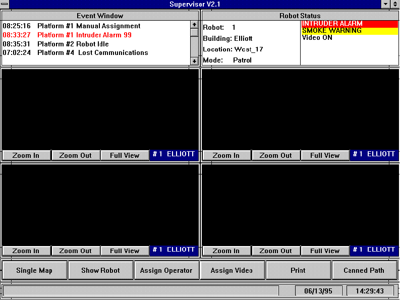
Figure 7. Screen dump of revised Supervisor Display running under Windows NT.
As an enhancement to the current automated attendant dial-out capability, a dial-in feature will be added in the very near future to allow a technician or supervisor to dial into the MRHA and obtain system status at any time using an ordinary touch-tone phone. A phone menu will present a variety of (diagnostic) options to include manual video switch control, detailed robot status, emergency dial-out configuration, and video tracking configuration. This dial-in capability will expand the maintenance technician's ability to remotely diagnose and possibly correct system problems without the need for costly travel or additional expensive test equipment on site.
This paper was delivered at Association of Unmanned Vehicle Systems, 22nd Annual Technical Symposium and Exhibition (AUVS '95), Washington, D.C., 10-12 July, 1995.
 Download the
compressed PostScript version of this paper (3.1MB).
 MDARS
MDARS
 Robotics at
Space and Naval Warfare Systems Center, San Diego