Petri net to PLC converting:
IO mapping and Validation
2021, Hugo Barroso & José Gaspar
Introduction
Designing Petri nets (PN)
with input/output (I/O) is a way of designing programs for PLCs. A PN with I/O
interacts with a system or, in other words, supervises a system. A PN typically
has inputs at the transitions and outputs at the places. See in figure1 the
arrows "PN actuation" meaning the outputs required to drive the
system and see "PN inputs" meaning the signals observed in the system
and used to drive the Petri net.
Figure1: Petri net supervising the system "HW to be
controlled".
This page provides a
software package that converts a PN with I/O to PLC-code, completed with
verification / validation features. Verification and validation are based on
reachability analysis and allow the assessment of error-free PN to PLC-code
conversion.
One challenge of doing
validation by reachability analysis is the so-called state space explosion. We
consider (accept) only bounded PNs based on the construction and analysis of
the coverability tree.
Concepts
The Petri net is
represented by its incidence matrix, D, and has inputs / outputs associated to
transitions and places, respectively. The matrix D has size n lines by m
columns, where n denotes the number of places and m denotes the number of transitions.
Matrix D=D+-D-. In code, the D+ and D-
matrices are usually denoted as Pre= D- and Pos= D+. The
initial marking is denoted as mu0.
Verification and validation
allow comparing the behavior of a PN with the discrete event system running on
a PLC, from a black box perspective: one generates PLC inputs and should obtain
PLC outputs as designed by the PN complemented with I/O.
The black box test involves
showing the PLC reaches all reachable states, by providing the right input
events at the right times. These events are automatically generated based on
the coverability tree of the PN.
Validation of the PLC
program means testing desired behaviors. These behaviors can be represented
also as PNs and therefore explored in conjunction with the PN implemented in
the PLC. Usually one creates a storyboard (a PN with I/O) which is combined
with the PN implemented in the PLC, and a complete system reachable set can
then be generated for a black box test.
Package Download and
First Test
[Instructions
for Windows]
Install
an SVN client, e.g. the freeware TortoiseSVN ** including its command line
tools **.
A reboot
may be required after installing TortoiseSVN.
In
Matlab run the following lines:
% go to a folder where you can receive files retrieved by SVN
% the next line is long (ends at /sww)
!svn co --username pn2plc
--password coverability
svn://svn.isr.tecnico.ulisboa.pt/dccal/msc/plc_verif/sww
cd sww
addpathx('.')
cd test
cd exp1_PN_sim
tst
Tests Contained in the
Repository
The design of the PNs with
IO, the starting point of our conversion and validation toolchain, is based on
the IOPT tools:
http://gres.uninova.pt/IOPT-Tools
Our PLC code production
toolchain is applied on the PNs with IO, therefore allowing to verify whether
the PNs are correctly translated to PLC ST programs.
The
repository contains three experiments in three separate folders:
exp1_PN_sim
exp2_IOPT_to_ST
exp3_PLC_Unity_tst
The first experiment,
in folder exp1_PN_sim, loads a PN with IO (a .pnml file), finds the
reachable set of the PN, and generates events to reach all possible states.
Figure 2 shows the results.

Figure 2: Test of a PN with IO. Top plot shows an automatically generated sequence that drives the PN through all the reachable states. The other two plots show the state of the PN and the generated outputs.
The second experiment,
in folder exp2_IOPT_to_ST, tests the conversion from PN to PLC-code
(Structured Text). Figure 2 shows a sample of lines of code generated. See the
full code in the folder, file "alarm_TEST_UNITY.txt".
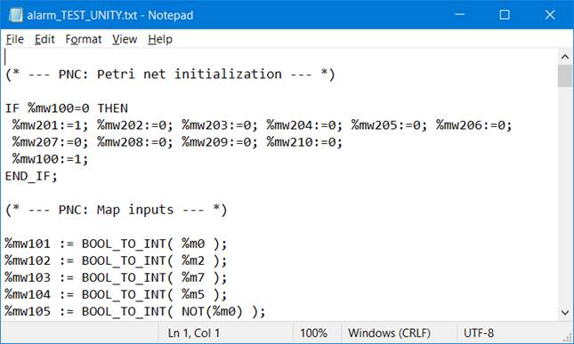
Figure 3: Sample lines of the PLC-code generated from a PN.
The third experiment,
in folder exp3_PLC_Unity_tst, involves the PLC development environment,
Unity Pro (v13), which is contacted by a client running in Matlab (see Figure
4).
|
(a) Setup with one input and one output modules
(b) Setup based on a single input and output module |
(c)
Simulated-hardware setup. The input and output are mapped on the PLC memory. |

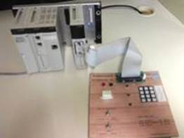
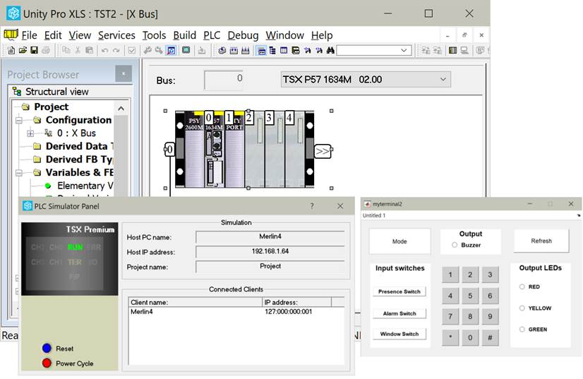
Figure 4: Schneider's PLC development
environment, Unity Pro, interacting with a client running in Matlab.
Maintenance &
Acknowledgement
This software is distributed
in the hope that it will be useful, but without any warranty; without even the
implied warranty of merchantability or fitness for a particular purpose.
In case you find this
software useful and do any publication in the sequel please cite the paper:
"Validation of
Discrete Event Processes implemented on PLCs based on Petri Nets", Hugo
Conde Barroso and José Gaspar, IEEE International Conference on Autonomous
Robot Systems and Competitions (ICARSC) 2021.
Contact
|
Prof. José Gaspar Instituto de Sistemas e Robótica, Instituto Superior Técnico, Torre Norte Av. Rovisco Pais, 1 1049-001 |
Office: Torre Norte do IST, 7.19 |