2nd Order Digital Controller on a
Arduino
+ Matlab Config & Monitor Interface
November 2015, José Gaspar
Introduction
In this page you can find a
second order digital controller implemented on an Arduino 2009 or Uno. The
controller is configured using the USB connection. A Matlab interface allows
also realizing a number of experiments such as obtaining step responses, open
or closed loop. This software helps the initial developing of the local control
of the physical setup used in the Distributed
Control Systems course.
Implementing a second order
digital controller can be done with a difference equation corresponding to a
transfer function:
![]()
where the coefficients a0
till b2 are set in accordance to the system at hand, G(z):
Figure1: System G(z) controlled by the feedback controller C(z).
Download and usage
Download the zip file ctrl_ord2_serial.zip and decompress it to a
folder of your choice.
Load the program ctrl_ord2_serial.ino
to the Arduino using the Arduino IDE. Note, you need to keep ctrl_ord2_serial.ino
in the folder ctrl_ord2_serial/.
as that is what is expected by the Arduino IDE.
Start Matlab and change to
the folder containing the files arduino*.m. Within Matlab you need to define the
serial port (USB connection). You usually find the COM port through the Arduino
IDE.
First usage example,
considering e.g. communicating through COM3:
>> arduino_ini('COM3'); arduino_end
Usage after uploading ctrl_ord2_serial.ino
to the Arduino:
>> arduino_ini; arduino_cmd({'C',
's', '<'}); arduino_end
Note: These instructions are
written for the Windows operating system. This distribution has not been tested
with Linux or OSX.
Example
In this example the circuit
to control is a first order RC series circuit, where R=10KOhm C=1microFarad.
The circuit is commanded by the PWM output in pin9. The command value and the
capacitor voltage are observed by the ADC0 and ADC1, respectively.
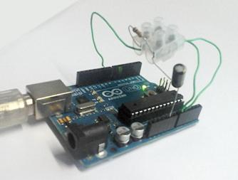
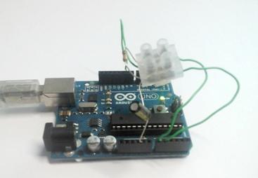
Figure2: RC-series circuit mounted on an Arduino.
The Matlab script is the
following:
close all
% acquire
and plot signals
arduino_ini('COM34')
arduino_cmd({'r0','s', 'r123', 's', '<'});
arduino_cmd({'r0','s', 'c00.5', 'C', 'r500', 'x', '<'});
arduino_cmd({'r0','s', 'c00.4','c1-0.1','c3-1', 'C', 'r500', 'x', '<'});
arduino_cmd({'c01', 'c10', 'c20', 'c30', 'c40', 'C'});
arduino_end
% just label
the plots
leg= {'PWM signal
(0..1024)', 'control signal (0..255)', 'capacitor charge (0..1024)'};
for i=1:3
figure(i)
if i==1, legend(leg{[1 3]}); else
legend(leg{2:3}); end
xlabel('Time [\mu sec]')
end
Explaining the commands
that Matlab is sending to Arduino:
'r0','s' - set reference to zero and run a null-step
actuation to discharge the capacitor
'r123', 's', '<' - set reference 123, acquire the
step response, and plot
'c00.5', 'C' - set a proportional controller with gain 0.5,
and show (print on screen) the controller expression
'c00.4','c1-0.1','c3-1' - set the coefficients of a PI
controller (0.4 - 0.1Z^(-1)) / (1 - Z^(-1))
'r500', 'x', '<' - set reference 500 and acquire a
closed loop response
'c01', 'c10', 'c20', 'c30', 'c40' - reset the controller to become
proportional with gain 1.0
The result of arduino_cmd({'r0','s', 'c00.5', 'C', 'r123', 'x', '<'}) , i.e. the open loop step response, is
shown in the next figure. Note that the Arduino has 10 bits ADC (values
0..1024), and PWM control of just 8 bits (0..255). Hence, the value of 123 is
approximately half of the maximum output (steady state of a low pass of the PWM
output).
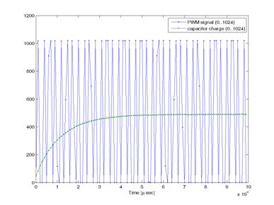
Figure3: Open loop response, showing samples of the PWM signal and of
the capacitor voltage.
The results of the two
controllers, proportional and PI, are shown in the next figure. Note that in
this case the reference value of 500 is compared with the range 0..1024. The
proportional controller is known to have nonzero steady state error as the system
does not have a pure integrator: see in the plot that the output converges to
about 330 instead of 500. The PI controller theoretically is expected to obtain
zero steady state error. Note that effectively the output converges to the
reference 500.
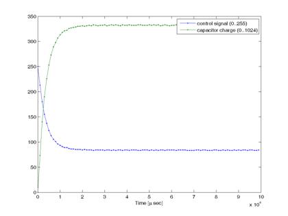
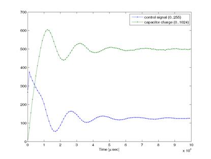
Figure3: Closed loop. Proportional controller (left). PI controller
(right).
Maintenance
This program was created
for the purpose of helping a control systems course. There is however no
continuous maintenance other than the requirements associated to the classes.
This program is distributed
in the hope that it will be useful, but without any warranty; without even the
implied warranty of merchantability or fitness for a particular purpose.
Acknowledgment
In case you find this
software useful and do any publication in the sequel please cite the paper:
Ekit - Tool for Learning
Signals, Circuits And Electronic Systems, Nuno Lucas, José Gaspar, João
Sequeira, in Proc. of IV Jornadas de Engenharia Electrónica e Telecomunicações
e de Computadores, pp35-40, November 2008, Lisbon, Portugal. PDF
file.
Contact
|
Prof. José Gaspar Instituto de Sistemas e Robótica, Instituto Superior Técnico, Torre Norte Av. Rovisco Pais, 1 1049-001 |
Office:
Torre Norte do IST, 7.19 |