Schneider Premium PLC Hardware Interfaces
& Signals Monitoring
October 2015, José Gaspar
Introduction
Schneider Premium P57 PLCs
can be equipped with various types of input and output modules. In the Industrial
Automation course the PLCs, P57 1634/2634, are equipped in two main
configurations:
(i) two separate discrete input and output modules,
namely the DEY16D2 and the DSY16T2, or
(ii) a single discrete input and output module, namely the DMY28FK.
The requirement to have
laboratories equipped for serving multiple shifts of classes is better served
if each group of students can plug / unplug their specific hardware terminal.
Figure1 shows terminal hardware used in the laboratories of the Industrial
Automation course. Separate wiring to each of the inputs and outputs make the
changes of hardware terminals slow processes and likely sources of wrong
connections.
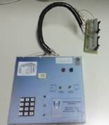
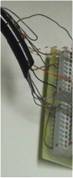
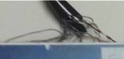
Figure1: Input and output based in single conductor wires. This solution
is still based in the use of screw terminals, which accounts for time consuming
and error prone plugging of terminal hardware.
The problem hardware
terminal changes is almost none for the DMY28FK, as it has I/O accessible by
flat cables (2x 20pin IDC), which can be easily plugged / unplugged at the
beginning / end of the classes. It is however an issue for the DEY16D2 and the
DSY16T2 as they have a screw terminal for each of the 16 input/output bits. The
modules DEY16D2 and DSY16T2 allow using terminal blocks, but that solution does
not allow fast interchange of terminal hardware with the module DMY28FK.
In this page is presented a
printed circuits solution to allow easy sharing (interchange) of terminal
hardware between the module DMY28FK and the modules DEY16D2 and DSY16T2. Printed
circuits are used to connect the IDC flat cables to individual wires by
soldering. Complementarily, inexpensive terminal strips can be used to connect
/ disconnect the individual wires to the terminal hardware.
Given the flat cables
interface, it is also shown (later in this page) an application where an
Arduino is used to monitor the input and output signals of a PLC.
Flat cables interface
Due to the personal
computer (desktops) market, 40wire flat cables are still nowadays inexpensive,
and very common to find and buy. 40wire flat cables were therefore chosen as
the interface on the side of the terminal hardware. Module DMY28FK offers 2x
20wire flat cable interfaces. Buying four 20wire female IDC plugs for each
40wire flat cable allows building two cables, each one allowing to connect one PLC to one terminal. See in figure2 (top row)
the connection between the DMY28FK and the hardware terminal. The PCB in the
hardware terminal side has a 40wire IDC-female to receive the 40wire IDC-male
of the cable.
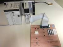
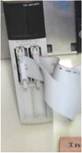
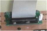
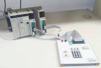
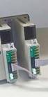
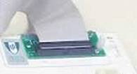
Figure2: Input and output based in flat cables. Top row shows the flat
cable connection between the DMY28FK and the terminal hardware. One PCB is used
to convert the flat cable into individual wires. Bottom row shows the flat
cable interface between the modules DEY16D2 and DSY16T2, and the terminal
hardware. In this case are used 3 PCBs, two to connect with the PLC modules and
the other one as before on the terminal side.
As referred, modules
DEY16D2 and DSY16T2 have screw terminals. Two PCBs have been developed to
convert screw terminals into 20wire IDC cables, which allow then the
inter-change of hardware terminal with the DMY28FK. See figure2, bottom row,
pictures of the final assembly of terminal hardware with the PLC.
Figure3 shows the manufactured
PCBs boards, adapting the inputs/outputs of the modules DEY16D2 and DSY16T2 to
the terminal hardware. Note that in the case of using module DMY28FK, the two
20wire IDC PCBs are not necessary, as the module interfaces are already in the
form of 20wire IDC.
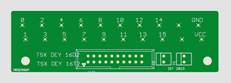
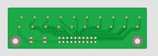
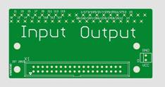
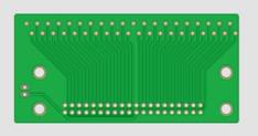
Figure3: PCBs for connecting individual wires to flat cables. Top row
PCBs allow using modules DEY16D2 and DSY16T2 with 20wire flat cables, similar
to the DMY28FK. Bottom row shows a 40wire interface to use on the terminal
side. Common 40wire flat cables link 40pin IDC to 2x 20pin IDC (the cables are
split in half at their middle length).
Cost
The cost of the PCBs, plugs,
components and cables, necessary to equip ten workbenches (PLCs), was in the
order of 300euro. IDC20 plugs, male and female, were found to be more expensive
than the IDC40 plugs - that was one of the reasons for selecting IDC40 on the
side of the terminal hardware.
Note that now the cost for
preparing more hardware terminals is reduced to just the IDC40 PCB. This low
cost is helpful as it allows having multiple shifts around the same PLCs, since
plugging / unplugging terminal hardware is fast and connections-error-free, as
required to be done at every begin / end of a class.
PLC Signals Monitor
The flat cables interface allows
inserting, and taking away, devices in between the PLC modules and the terminal
hardware in a fast and connection-wise error-free manner. A device frequently
necessary to insert in the circuit is the signals generator and monitor.
Generating and monitoring the signals between the terminal hardware and the PLC
is of particular importance for systematic testing and debugging of
applications.
Figure4 shows a PLC signals
monitor built with IDC40 interfaces to be inserted between the terminal
hardware and the PLC. The monitor is based in an Arduino Mega and some hardware
converting 5VDC to/from 24VDC. The monitor records all signal changes found in
the digital signals generated by the PLC and by the terminal hardware. The
monitor is also able to generate signals and in that way simulate signals that
make the PLC program work in a specific sequence and therefore help debugging
the application.
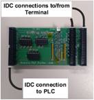
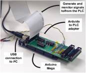
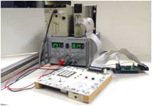
Figure4: PLC input and output monitor and signals generator. PCB with
the IDC interfaces (left). Generator mode requires a single flat cable
(middle). Pass-through mode, the monitor records signals generated by the PLC
and the terminal hardware.
Downloads
** Not yet
available **. Under
study the way to make publicly available the hardware here described.
Maintenance
The hardware described in
this page was created mainly for the purpose of helping classes. There is no
continuous maintenance other than the requirements associated to the classes.
The information and files
in this page are distributed in the hope that they will be useful, but without
any warranty; without even the implied warranty of merchantability or fitness
for a particular purpose.
Acknowledgments
Thanks to Henrique Gonçalves, Manuel Ribeiro and
Ricardo Nunes for helping with the design and the
implementation.
Hardware was mostly
financed by the Systems, Control and Decision scientific area of the EEC Department.
In case you find this
material useful and do any publication in the sequel please refer to the course
Industrial
Automation at Técnico,
Contact
|
Prof. José Gaspar Instituto de Sistemas e Robótica, Instituto Superior Técnico, Torre Norte Av. Rovisco Pais, 1 1049-001 |
Office: Torre
Norte do IST, 7.19 |