Industrial Automation Course at ULisboa
Use Ethernet to Log PLC Strings
2023
José Gaspar
Introduction
This webpage has the purpose of
providing one coding example where one PLC creates text messages which can be
logged by a remote PC. The logging is realized with a Matlab function, running
in the PC, that uses the ethernet connection to poll the memory of the PLC. The
connection protocol is Modbus.
Log
PLC Strings Generated by the PLC Simulator
Download
the Unity Pro project stored in the zip file
and unzip
it. After downloading and unzipping the project, compile and transfer the
project to a simulated PLC (part of Unity Pro). Then launch the Matlab function
myterminal5, see Figure 1(a).
Running myterminal5 allows showing a string created by the PLC. Unity
Pro allows the PLC to generate other strings. In Matlab:
myterminal5 > mymenu > Log final strings
allows
collecting (logging) a sequence of strings. Explanation: Matlab / myterminal5
are constantly polling the PLC memory and save any novel strings appearing in
the PLC memory.
|
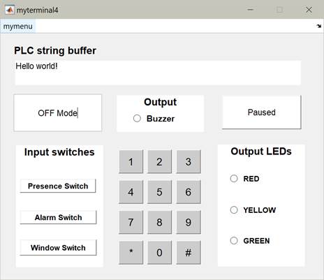
(a) Virtual terminal that
communicates with the PLC. Keys are available provided keyboard columns are
energized. The PLC string buffer, a null terminated string starting at
%MW190, is displayed when the terminal is "Running". |
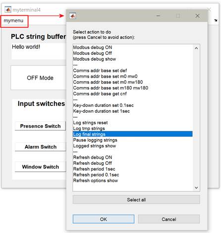
(b)
Options for communication, simulation times, strings logging and terminal
refresh. The commands "show" report mostly on the Matlab command
line. Command "Logged strings show" reports in a new window. |
|
Fig.1:
Virtual terminal running in Matlab connects to the PLC simulator using Modbus
(a). The virtual terminal allows logging strings after activation of option
"Log final strings" (b). Logged strings display is available by
clicking "Logged strings show". |
|
Log
PLC Strings generated by the real PLC
To avoid IP address
conflicts among many groups running the same code, the project (zip file
provided above) does not have the IP address configured. Therefore,
using the real PLC involves
configuring its IP address. Detailed
instructions to configure the IP address of the PLC:
http://www.isr.tecnico.ulisboa.pt/~jag/course_utils/plc_ip/p57_set_ip.htm
Having followed the instructions of the webpage
indicated in the previous paragraph to set the IP address, one would already
have the Matlab interface configured to connect to the PLC, using ethernet.
However, if one restarts Matlab, the connection information is lost, and
therefore one needs to inform Matlab, once more, about the IP address:
myterminal5
> mymenu > PLC IP change by hand.
Details
of Mixing Hardware IO with Virtual IO
Simulated
(virtual) IO allows developing and testing the PLC programs without the real
PLCs. The Matlab interface shown in Figure 1, effectively writes and reads
binary memories (and words) of the PLC. The list of binary and word memories used
in the PLC is easily shown in Matlab with:
myterminal5 > mymenu > Comms show addr and ip
The mixture
of hardware and virtual IO is based on two structured text sections, to be run
as the first and last sections of the Unity Pro (PLC) project. The first
section, mix_IO_ini sets each
input to true in case a binary memory indicates that. The last section, mix_IO_end reports to memories the current state of the
real outputs and resets the real inputs to the original values before the
overwriting guided by binary memories.
Explanation: The simulated
IO uses memories %M0 till %M19 (type EBOOL) where Matlab reads PLC information
(as PLC generated outputs) and writes simulated inputs. In addition, memory
words %MW180 till %MW199 (type INT) are used for communicating words and text
(strings). The referred PLC program sections, mix_IO_ini and mix_IO_end, (provided in the zip linked in the top of this webpage) implement simultaneously
real and simulated IO, by adding in the beginning of the scan cycle code as
%m20:= %i0.2.0; %i0.2.0:= write_input_ebool( %i0.2.0 OR %m0
);
and at the end of the
scan cycle code as
%m10 := %q0.4.0; %i0.2.0:= write_input_ebool( %m20 );
This code is adapted and
repeated for 8 inputs and 8 outputs.
Maintenance
The
software offered on this webpage was created for the purpose of being used in
classes. There is no continuous maintenance other than the requirements
associated to the classes.
This
program is distributed in the hope that it will be useful, but without any warranty; without even the implied warranty of
merchantability or fitness for a particular purpose.
Acknowledgment
In
case you find this software useful and do any publication in the sequel please
refer to the course Industrial
Automation at Instituto Superior Técnico, Universidade
de Lisboa, Portugal.
Contact
|
Prof. José Gaspar Instituto de Sistemas e Robótica, Instituto Superior Técnico, Torre Norte Av. Rovisco Pais, 1 1049-001 |
Office: Torre Norte do IST, 7.19 |