PLC IO Interface
Experiments:
(i)
7-Segments (ii) Visible delay
December 2017, José Gaspar
Abstract
This page details a hardware setup that allows students testing the actuation of a 7-segments display and a RC circuit from a PLC. The 7-segments display is shown mostly to make clear that PLC outputs are readily available. The RC circuit illustrates an important property of PLCs having IO based on transistors: the input and output impedances make hard parasite capacities to create large delays between interconnected PLCs.
Please consult laboratory work in:
http://users.isr.tecnico.ulisboa.pt/~jag/courses/api18b/api1819.html#lab
Introduction
The setup is based on Schneider Premium
PLCs equipped with 24VDC IO modules. In a previous project the PLC IO has been
made available by a 40wire ribbon cable. The ribbon cable can than be stripped
on the required wires to connect to a 12 ways terminal block. Figure 1 shows
the ribbon cable providing connections to 2 inputs, 2 outputs, and external
power. As it is common in mini PLCs (not micro PLCs) the IO requires external
powering, which is given to the PLC IO through 2 wires in case of a single IO
module, or through 4 wires in case of two modules (separate I and O).
Figure 1: Ribbon cable interface allowing access to two PLC inputs and two PLC outputs.
7-Segments display
The PLC outputs are 24VDC, and therefore
one needs a resistor before connecting to any of segment the 7-segments digit
display. In the laboratory are provided 3.9KOhm resistors that give a
reasonable compromise between making the segment visible and not making the
segment conduct too much current.
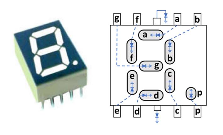
Figure
2: Common cathode 7-segments display.
RC circuit making a visible delay
While most courses will teach to use high
input impedance, one finds that in PLC input modules as Schneider DEY16D2 or
DMY28FK actually have low input impedances. The referred
modules have impedances about 6KOhm (as a comparison, an Arduino has much more
than 1MOhm input impedance).
The circuit of Figure 3 represents a PLC
output connected to a PLC input. Resistor R2 is a simplified representation of
the input impedance of a PLC.
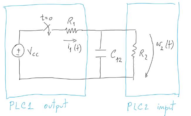
Figure
3: Simple model of PLC input and output connected, having in between a
capacity.
Despite being a simple model, Figure 3
already provides nice insights. In particular the
equivalent Thevenin impedance around the capacitor is the parallel R1//R2 and
therefore cannot be larger than R2. A time constant (R1//R2)*C12
cannot be larger than R2*C12. In case of something wrong, one could have a
large R1, but a visible time constant of 1sec would imply a capacitor of about C12=1/R2,
i.e. about 0.17mF, i.e. a too large capacity to be made by a
"parasite".
Acknowledgments
In case you find this material useful and do any publication in the sequel please refer to the course Industrial Automation at Técnico, University of Lisbon.
Contact
|
Prof. José Gaspar Instituto de Sistemas e Robótica, Instituto Superior Técnico, Torre Norte Av. Rovisco Pais, 1 1049-001 |
Office: Torre Norte do IST, 7.19 |