Turing Machines
Simulation:
Busy Beaver
November 2016, José Gaspar
Abstract
In this page is published one simulator of a Turing Machine and two examples of Turing Machines, namely (i) the 3-states 2-symbols busy beaver and (ii) the 4-states 2-symbols busy beaver. All code is developed in Matlab.
Introduction
A Turing Machine is a conceptual machine developed in the framework of Automata Theory. Its name is a tribute to Alan Turing (1912-1954). One of the reasons for the invention of the Turing Machine was the need to prove, in formal terms, that the Halting Problem, i.e. the problem of determining whether a generic program arrives to the halting state, is undecidable. In other words, it is not possible to build a machine that looks to a computer program and determines, faster than running the program, that the program arrives to the end or even that it has an end. In other words, at the time of Alan Turing (and still today, and for the future), if someone brings a program and an "infinite" empty tape to hold the program inputs and outputs, it is not possible to tell automatically that the program runs in a minute, runs in a day, runs for years, or never stops.
A Turing Machine (TM) has four main components: (1) Infinite length magnetic tape, (2) Read/Write head, (3) Rules table / FSM and (4) State register. See Figure1.
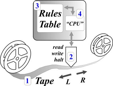
Figure1: Graphical representation of a Turing Machine, numbering the four main components.
Note that, in particular, a TM is not just an FSM. Not to forget other differences, for instance the TM contains also an infinite memory, in the form of a magnetic tape. While it is possible for a TM not using the magnetic tape, i.e. not writing to it, and therefore become similar to just the FSM, the opposite is not possible: a FSM has not the option of reading and saving information in memory (e.g. tape) and is therefore limited to be memory less, besides its knowledge about its current state.
The Busy Beaver Turing Machine is an example of a Turing Machine (TM) which is built with the objective of filling an empty TM tape with as many as possible ones, using a rules table (FSM) with a minimum number of states [BB-Wikipedia] [BB-Catonmat]. Note that the Halting Problem is considered while designing a Busy Beaver: a Turing Machine is only considered to be a Busy Beaver if it halts (stops). In addition a Turing Machine is only a Busy Beaver if for a certain number of states it reaches the maximal possible number of ones written into the tape.
Figure 2: A graphical representation of the Busy Beaver problem. The Beaver has the task of moving itself and dropping in different places, as many as possible, "wooden logs" (writing ones in a TM tape). The hard part of the problem is the requirement to reach the Halt state while using a minimal FSM.
One implementation of the 3-states 2-symbols Busy Beaver is shown in Figure 3. We use the busy beaver finite state machines described in [BB-Wikipedia] and [BB-Catonmat]. The 2-symbols tag means that the magnetic tape handles just 0 or 1 values. The 3-states are named, as usual, A, B and C. The rules table, Finite State Machine (FSM), can be shown graphically (Figure 3, left), or in the table format (Figure 3, right).
|
|
|

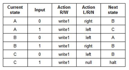
Figure 3: Example of a 3-state 2-symbol Busy Beaver. See two representations, a graphics one (left) and a table format (right). Notice that this FSM always writes the value 1.
Implementation of the Simulator
As previously referred, a TM has four main components: (1) Infinite length magnetic tape, (2) Read/Write head, (3) Rules table / FSM and (4) State register. Understanding the roles of the tape and the FSM is the critical path to get an insight to the TM.
The TM magnetic tape has five basic operations, namely moving Left/Right/None and Reading/Writing a single bit. In the following Matlab code is shown a simulated interface to a tape. Comparing to a real interface, which would have a real tape (and its memory), the simulated interface contains itself a replacement for the tape memory.
function ret= TM_tape( op, arg1 )
% Tape for a Turing machine. Basic operations:
%
read/write and move Left/Right/None
global TMT; if isempty(TMT), TM_reset; end
switch op
case 'reset', TM_reset;
case 'left', TMT.pos= TMT.pos+1;
case 'right', TMT.pos= TMT.pos-1;
case 'null_move' % do nothing
case 'read‘, % read one bit
realloc_if_needed( TMT.pos );
if TMT.pos>=0, ret= TMT.val( TMT.pos+1
);
else ret= TMT.valNeg( -TMT.pos
);
end
case 'write‘, % write one bit
realloc_if_needed( TMT.pos );
if TMT.pos>=0, TMT.val( TMT.pos+1 )=
arg1;
else TMT.valNeg( -TMT.pos )=
arg1;
end
otherwise, error('inv op')
end
The interface to the tape provides all the functions required by the FSM. More precisely, the tape bits work as conditions for the evolution of the FSM and the FSM can (and does) change the tape bits.
In the following is shown a FSM representing the 3-states 2-symbols Busy Beaver. The rules table (FSM) has five columns and the number of lines correspond to two times the number of states (at each state can be observed two symbols). The five columns have the following information: (i) current state, (ii) jumping condition, (iii) action of tape writing, (iv) action of tape moving, and (v) next state. In our implementation, the actions are in a single column and therefore our FSM has just 4 columns.
function FSM= def_BusyBeaver3
% FSM has four columns: curr_state,
true_false_condition, actions, next_state
%
|- T/F cond -----| |- write
action and move action ----|
FSM= {
'A', 'TM_tape("read")==0', 'TM_tape("write",1);
TM_tape("right");', 'B';
'A', 'TM_tape("read")==1', 'TM_tape("write",1);
TM_tape("left");' , 'C';
'B', 'TM_tape("read")==0', 'TM_tape("write",1);
TM_tape("left");' , 'A';
'B', 'TM_tape("read")==1', 'TM_tape("write",1);
TM_tape("right");', 'B';
'C', 'TM_tape("read")==0', 'TM_tape("write",1);
TM_tape("left");' , 'B';
'C', 'TM_tape("read")==1', 'TM_tape("write",1);
TM_tape("null_move");', 'halt';
};
To use the FSM just introduced, one just needs to
check the lines whose first column match the current state, and for those lines
one just needs to check which of the jumping conditions is true (must be only
one; otherwise there is an error in the definition of your FSM). For example,
if the FSM is now in state B, then the relevant lines are the lines 3 and 4,
and if the tape has a 1 at the current position then line 4 is the only that
serves. Consequently, the actions in line 4 are writing 1 to the tape (which is
useless, as the tape already has a 1 at that position) and moving the tape one
position to the right. Finally, the FSM jumps to (more precisely, continues in)
state B.
The description just done of the FSM is too much
verbose. In essence one can use a very compact representation based in just 5
characters: one character for current state (A, B, C, ...), one character for
symbol read (0 or 1), one character for symbol to write (0 or 1), one character
to denote the tape motion (L, R or N) and one character for the next state (H
or A, B, C, ...). For example, the first line of the FSM list just shown can be
represented simply as 'A01RB'. The compact representation of the complete FSM is
therefore:
function FSM= def_BusyBeaver3
tbl= {'A01RB', 'A11LC', 'B01LA', 'B11RB', 'C01LB', 'C11NH'};
FSM= convert_table_to_list( tbl );
Given the tape function and the FSM encoding, one just needs a function to run the FSM together with the tape. In our case the detailed (verbose) representation of the FSM contains all the needed interface to the tape, and the TM runner does not even have to know it is interacting with a tape. In our Matlab programming, the "eval" function runs code listed in the FSM, without knowing it contains all the needed handling of the tape.
function
TM_run
FSM=
TM_ini( ‘BusyBeaver3'
);
TM_tape(
'reset' );
curr_state=
FSM{1,1};
while
~strcmpi(curr_state, 'halt')
for
i=1:size(FSM,1)
if
strcmpi(FSM{i,1}, curr_state) ...
&& eval( FSM{i,2} )
% found state and true condition
eval( FSM{i,3} );
% curr_state <- next
state
curr_state= FSM{i,4};
break;
end
end
end
The complete simulation code and a couple of demos can be found in the download section. To see more details on the state of the art Busy Beavers, please check the competition results summarized in [BB-competition].
Download and Usage
Download the zip file TM_BusyBeaver.zip and decompress it to a folder of your choice.
To run the main demo:
>> TM_run
After running the demos, the resulting figures are similar to the ones shown in Figure 4. Figure 4 shows the state of the tape as time progresses and the TM advances its work, according to the FSM.
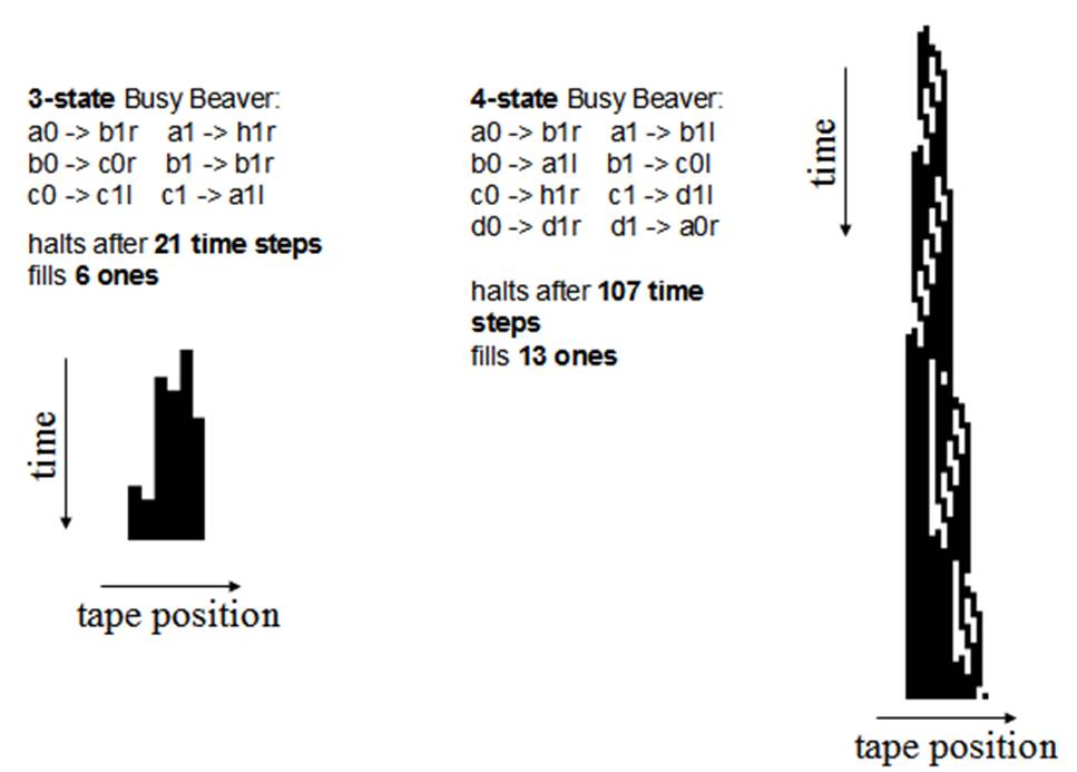
Figure 4: Busy Beaver demos. The 3-state 2-symbol and the 4-state 2-symbol Busy Beavers, create the tape state evolutions shown in the left and right, respectively.
The images in Figure 4 are very similar to, but do not match exactly with, the ones found in [BB-Catonmat]. Our plots have a horizontal mirroring as compared to those of [BB-Catonmat]. At the time of writing this page, our implementations and the busy beaver implementations at [BB-Wikipedia] and [BB-Catonmat] have the same finite state machines, and therefore the differences are not in the FSM.
The difference of our output, with respect to the one found in [BB-Catonmat], is likely to be due to the interpretation of the move the head left or right. In our case the "move tape left" is implemented as "increment the read/write header one position" (and similarly, "move tape right" is implemented as "decrement the read/write header one position"). Reversing the implementations of the tape moving, i.e. exchanging L to R and vice versa, would be enough to obtain equal graphics.
Links
[BB-Wikipedia] Busy Beaver, https://en.wikipedia.org/wiki/Busy_beaver (last visited November 2016)
[BB-Catonmat] The Busy Beaver Problem, http://www.catonmat.net/blog/busy-beaver/ (last visited November 2016)
[BB-competition] The Busy Beaver Competitions, http://www.logique.jussieu.fr/~michel/bbc.html (last visited November 2016)
Acknowledgments
In case you find this material useful and do any publication in the sequel
please refer to the course Industrial
Automation at Técnico,
Contact
|
Prof.
José Gaspar Instituto de Sistemas e Robótica, Instituto Superior Técnico, Torre Norte Av. Rovisco Pais, 1 1049-001 |
Office: Torre Norte do IST, 7.19 |